OptoScope SC-10 Systems
3D View
Description
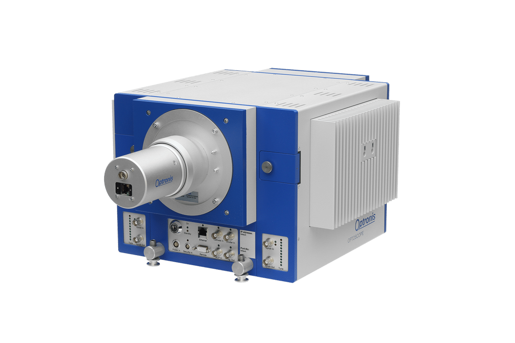
SC-10 systems are based on the SC-10 main unit. These systems provide a high degree of flexibility and cover a large range of applications. High temporal resolution of 2 ps can be obtained. The main unit integrates a streak tube with quartz input window to allow light detection from UV to NIR. Sweep units for triggered operation as well as synchroscan operation are available. Furthermore, it is possible to add a second sweep unit with orthogonal deflection.
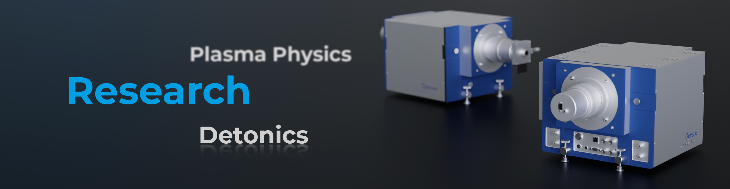
SC-10 systems are well suited for time resolved spectroscopy as they are flexible and they provide a wide range for optical coupling. For applications in detonics and plasma physics the 2-dimensional active area can be used to image the target area and consequently to simplify alignment.
More product information

Streak systems based on the SC-10 main unit are flexible and can be configured for various applications. Sweep unit can be easily exchanged and therefore simplifies system reconfiguration by the user. The SC-10 main unit itself is combined with an electro-magnetic shutter and image intensifier to allow single photon detection. Spectral sensitivity can be adapted to the application by selecting the type of photocathode. Optionally, a photocathode gating function can be implemented.
Main unit SC-10 ![]()
Shutter SH25-10
Image Intensifier II125
Photocathode /S20, /S25, /BI, /S20LN
Photocathode gating /PB (optional)
Input optics
Visible range IOV-10 ![]()
UV and visible range IOU-10 ![]()
Sweep units
Triggered, high temporal resolution TSU11-10 ![]()
Triggered, low temporal resolution TSU12-10 ![]()
Synchroscan SSU11-10 ![]()
Sweep units (orthogonal)
Triggered, fast TSU21-10 ![]()
Triggered, slow TSU22-10 ![]()
Elliptical sweep SBU21-10
Readout camera
CMOS sensor SRU-BC ![]()
sCMOS sensor SRU-E* ![]()
Control
StreakViewer Software ![]()
OptoAnalyse Software (obsolet) ![]()
Hardware PC according to customer requirements
Below you will find typical examples. Only a small fraction of all possible applications can be shown. For particular requirements, optimized configurations can be proposed.

SC-10/S25 with IOV-10/M and TSU11-10 as well as SRU-ED
Temporal resolution: <2 ps (single-shot) / <5 ps (repetitive)
Timebase: 200 ps – 20 ns
Wavelength: 350 nm – 950 nm
Trigger frequency: 0 – 2.5 kHz
Frame rate: 0 – 150 Hz
Field of applications: Semiconductor material research, laser and plasma physics, research in Chemistry and Biology

SC-10/S25/PB with IOU-10 and TSU12-10/PG as well as SRU-BA/SRU-BC
Temporal resolution: <20 ps (single-shot) / <25 ps (repetitive)
Timebase: 5 ns – 100 ms
Wavelength: 200 nm – 950 nm
Trigger frequency: 0 – 100 kHz
Frame rate: 0 – 15 Hz
Field of applications: Plasma physics, research in Chemistry and Biology, detonics

SC-10/S20 with IOU-10/M and SSU11-10 as well as SRU-BA/SRU-BC
Temporal resolution: <2 ps
Timebase: 300 ps – 2 ns
Wavelength: 200 nm – 850 nm
Synchroscan frequency: 80 MHz
Frame rate: 0 – 15 Hz
Field of applications: Laser physics, research in Chemistry and Biology

SC-10/S20/PB mit IOV-10 und SSU11-10, TSU21-10 sowie SRU-ED
Temporal resolution: <2 ps
Timebase: 300 ps – 1 ns
Wavelength: 350 nm – 850 nm
Synchroscan frequency: 250 MHz
Trigger frequency: 0 – 10 KHz (orthogonal)
Timebase: 10 ns – 1.5 µs (orthogonal)
Frame rate: 0 – 150 Hz
Field of applications: Synchrotron beam diagnostics

SC-10/S25 with IOV-10 and SSU11-10, spectrometer as well as SRU-ED
Temporal resolution: <2 ps (neglecting dispersion of spectrometer)
Timebase: 300 ps – 2 ns
Wavelength: 350 nm – 950 nm
Spectral range: 90 nm (300 gr/mm)
Synchroscan frequency: 80 MHz
Field of applications: Time resolved spectroscopy
Trigger Configurations
The temporal resolution of streak camera systems is determined by the streak camera itself but also by the trigger configuration used to synchronize the camera to the optical signal. When selecting the trigger configuration, trigger delay and temporal relation between optical and electrical signals need to be considered. Therefore, the selection of light source or exciting laser system has to be completed priot to consider a particular trigger configuration. This description provides an overview of typical setups.
Ask here for “AN-Trigger Configurations for Streak Cameras V2”.

Trigger Configuration with Amplified Lasers
Laser systems consisting of a high repetition rate Femtosecond seed laser and a low repetition rate amplifier have particular characteristics simplifying the precise synchronization of streak cameras. Particularly, if for longer trigger delay of the streak camera has to be taken into account, trigger jitter can be minimized to maintain good temporal resolution.
Ask here for “AN-Trigger Configuration for Amplified Laser Systems”.

Temporal Dispersion of Spectrometers
The combination of streak cameras with spectrometers allows the simultaneous measurement of wavelength and temporal pulse form of optical radiation. For this time resolved spectroscopy Cerny-Turner type spectrometers are typically used for wavelength separation. Inherent of these grating spectrometers is their impact on temporal resolution. This impact is described.
Ask here for “AN-Time-Dispersion of CT-Spectrometers”.
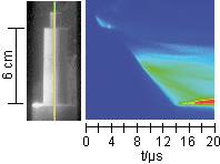
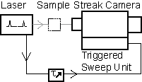
Detonation Velocity of Explosives
The article describes how a streak camera is used to measure the detonation velocity by observing the optical radiation emitted from an explosive compound. Detonation velocity is a key characteristic of explosives and describes the velocity a chemical reaction propagates through the material. During the explosion a slit image is streaked to provide temporal and spatial information. As sweep speed can be selected over a large range, detonation velocities of slow but also very fast energetic materials can be measured.
Ask here for “AN-Detonation-Velocity”.

TDC
The TDC is used to delay trigger signals and to generate trigger signals when combined with lasers integrating amplifiers or pulse pickers. Streak systems with the TSU12-10 can take particular advantage of the TDC. A detailed description of operation and functional principles is given with “AN-Trigger Configuration for Amplified Laser Systems“, available on request.
Datasheet ![]()
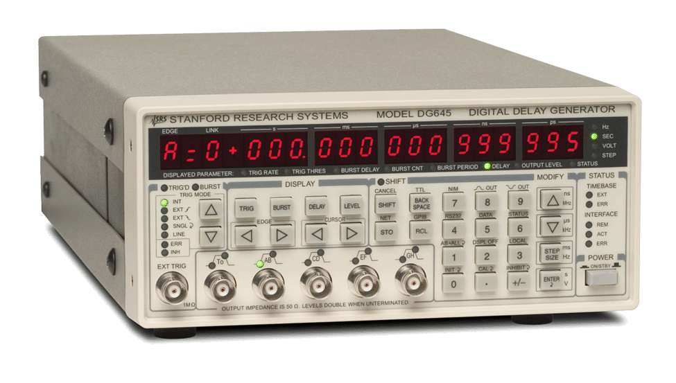
DG645
The programable delay and pulse generator DG645 (Stanford Research Systems) can be used for systems integrating the TSU12-10, TSU21-10 and TSU22-10 sweep units. In combination with the TSU11-10 jitter characteristics of the DG645 need to be considered. The DG645 can effectively be employed when externally triggerable light sources are used.
Datasheet ![]()

TRRC1
The TRRC1 is a passive delay line. The operation principle inherently does not add trigger jitter. Particularly for systems using the TSU11-10 maintain high temporal resolution in repetitive trigger mode.

CFD with LJPD/VI
Combined with a photodiode LJPD/VI the CFD can provide low jitter trigger pulses as well as a low jitter synchronization signal. The functional principle (constant fraction discriminator) minimizes trigger jitter related to pulse amplitude fluctuations.

LJFD/N
The LJFD/N is a frequency divider with adjustable division ratio. The device has a very low jitter between input and divided output signal. The LJFD/N has an additional input to enable single pulses to pass the device with very low jitter also.

LJFD/H2, LJFD/H4
The frequency dividers LJFD/H2 and LJFD/H4 are used to divide high frequency signals. The division ratio is fixed to 2 when using the LJFD/H2 and to 4 if the LJFD/H4 is used. Selection of output frequency is application specific.

LJFM
For frequency conversion for example from 125 MHz to 250 MHz the low jitter frequency multiplier LJFM is used. Input and output frequency can be selected according to application requirements.

Spectrometer
For time resolved spectroscopy systems, different spectrometers can be combined with the SC-10. HRS spectrometers (Princeton Instruments) are shown as typical example. Model and grating selection can be done application specific.
Teledyne HRS-Series ![]()
Teledyne IsoPlane 160 ![]()
Horiba JY iHR-Serie ![]()

COUP-TS
In order to position a streak system as detector on a spectrometer output, the COUP-TS can be used. This allows fine adjustment in two directions parallel to the optical table. Mounting cylinders are provided with the COUP-TS. They are fixed on the spectrometer to set the optical axis to the appropriate height.
Datasheets SC-10 System
SC-10 Main Unit
IOV-10 Input Optics
IOU-10 Input Optics
TSU11-10 Sweep Units
TSU12-10 Sweep Units
SSU11-10 Sweep Units
TSU21-10 Sweep Units
TSU22-10 Sweep Units
SRU-BC Readout Camera
SRU-E Readout Camera
SreakViewer Control
Datasheets Accessories
3D Models
The components of the SC-10 based streak System are available as 3D models in STEP and DWFX Format. Please ask here for the relevant components and format. We will be happy to send you the data.
Software
Select the appropriate version for the readout camera you use. The manual provides information on compatibility with operating systems. Please note that downloading and use of the program and manual is only permitted as part of an update or when trialing a product.
OptoAnalyse/B V4.01 for SC-10 Systems with SRU-BA or SRU-BC 
OptoAnalyse/E V4.00 for SC-10 Systems with SRU-E* ![]()
OptoAnalyse/SE V3.75 for SC-10 Systems with SCRU-SE or SCRU-SE-A 
OptoAnalyse/PX V3.92 for SC-10 Systems with ANIMA-PX/25 
OptoAnalyse Handbuch für aktuelle Version 
OptoAnalyse/CI Manual of currently released /CI Option
Software for previous systems with SCMU-ST
Select the appropriate version for the readout camera you use. The manual provides information on compatibility with operating systems. Please note that downloading and use of the program and manual is only permitted as part of an update or when trialing a product.
OptoAnalyse/B V3.41 for SCMU-ST Systems with SRU-BA
OptoAnalyse/SE V3.41 for SCMU-ST Systems with SCRU-SE or SCRU-SE-A
OptoAnalyse/PX V3.41 for SCMU-ST Systems with ANIMA-PX/25